Energy efficiency was, is and will be one of the major topics of interest for modern society. In absolutely any industry, regardless of field of activity every company aims, through the products they sell, how they consume less power and offer higher performance as well. Power factor is one of those factors that can seriously affect the energy efficiency in different electrical systems, unless actions are taken, as we will see below.
Before to turn on technical side, I try to present an analogy, so you will understand what is actually the power factor. In our little experiment, we consider a trolley that goes like a train on railway and can be towed by a person (Fig. 1). As we know, regardless of the person’s position the trolley will not change direction, of course, we exclude idea that trolley jump off the railway.
fig. 1
If the person that tow the trolley is not exactly in the middle of the rails, always between personal position and travel direction of the trolley will be an angle, which in fig. 1 I noted as . Now we propose some possible situations where you can find the person, while towing the trolley.
Situation 1. In this situation we consider that the angle between the position of the person who tows the trolley and its direction of travel is very large, tends to 90 degrees (Fig. 2) .When the person begin to tow the trolley will not be at all surprised that he has
fig.2
made a serious effort, that will consume enough from his energy and the trolley will move very little, even more, when the angle is exactly 90 degrees will make all the energy that holds and the trolley will not move at all. If we had installed a energy meter this will record all the energy consumed, even though the trolley movement is almost 0.
Situation 2. Being in the situation 1, the person will not accept to tow the trolley in such conditions, completely unfavorable to him and step by step he will move slightly toward the center of the rails where the angle between its position and trolley direction tends to be zero degrees (Fig. 3). As moving closer to the center of the rail it will realize that the
fig. 3
effort is reflected in the trolley movement and moreover when the angle becomes zero realizes that all the energy consumed for tow the trolley is reflected in moving it and of course it will try to maintain this position around zero. This time our energy meter record the same energy consumed but the trolley moved as was expected.
Similar situations happens on electrical systems that contain nonlinear circuit components (coils, capacitors, diodes, transistors, etc.) which are divided into passive components (coils, capacitors) and active components (diodes, transistors, etc). We are going to disscus exclusively about passive components, because they are widely used in different electrical circuits (ex.electrical motors) and are big energy consumer.
In circuits where voltage and current are alternative depending on the nature of load, power can be defined as follows:
– putere aparenta [VA]
– putere activa [W]
– putere reactiva [VAR]
these are the power ecuations for single phase supply, in case of three phase supply we have:
– putere aparenta [VA]
– putere activa [W]
– putere reactiva[VAR]
If we calculare the ratio between active power and apparent power we obtain power factor:
Now if you take a look at the situation with the trolley we see very clearly that when the angle was close to 90 degrees we consumed an amount of energy, but the movement was very low, or even zero when = , this produces a power factor cos very small or even zero if the angle reaches 90 degrees, after that in the situation 2 the angle decreased and tended to degrees, energy consumption was reflected in the movement of trolley = , produces a power factor cos = 1, in short I spent the same energy as in the previous case but trolley moved a lot more. So in conclusion, in order to be as much as efficient in terms of energy consumption we must find solutions so as to keep this angle as close degrees, that means a power factor cos that is closer to 1. This power factor is strongly influenced by the presence of reactive circuit elements capacitors and coils, which are the main “culprits” that the value is different from 1. Coil is leader this top since is present in electric motors construction, so in most cases we must correct an inductive power factor. If we look purely to the mathematical relationships of the three powers, we see that there is the following equality, which is also known as the power triangle:
The two circuit components (coil and capacitor) behave differently but both introduce a phase shift of 90 degrees between voltage and current, the voltage across the capacitor is behind the current 90 degrees and the electrical current through the coil being behind the voltage with 90 degrees, which is very useful in our case if we want to correct an inductive power factor we will introduce a capacitor and similarly for a capacitive power factor we will introduce a coil(fig. 4).
fig. 4
In fact to apply a power factor correction means to “force” the two alternative quantities voltage and current to oscillate in phase, the phase shift between them to be zero or very close to zero.
Calculation exemple
As I already mentioned in most cases we must correct an inductive power factor that is created by coils, the most common example is the electric motors. Usually on the rating plate given by manufacturer this power factor is marked with values between (0.6-0.9), together with other data related to motor. So let’s take for example an asynchronous electric motor with 30 kW active power supplied at a voltage of 400 volts at 50 Hz frequency and power factor cos = 0.8. As I already stated above, being an inductive power factor correction will have to introduce in circuit a capacitor to bring the value of cos closer to 1. For this we need to find reactive power and of course what is the value of capacitor to be introduced in the motor circuit. The reactive power can be deduced from the power triangle relation:
So far in this relation we do not know the value of apparent power but we can deduce it very simple from active power:
Thus the apparent power is:
Finally reactive power is:
In conclusion it will be necessary to introduce in the motor circuit, in paralel with it a capacitor, that produce the equivalent of 22.5 [kvar] capacitive reactive power. How to find the capacitor value? Well quite simply, if we turn to the reactive power equation and rewrite it in another form we have the following equivalence formula:
As seen in the above equation we introduced a new term [] called electrical reactance – which can be, inductive reactance for coils and capacitive reactance for capacitors. The equations of the two reactance are as follows:
inductive reactance:
capacitive reactance:
where:
– angular velocity [rad/s]
L- coil inductance [henry]
C- capacitor capacity [F]
f- frequency [Hz]
In our case we are interested in capacitive reactance in order to introduce it into the reactive power equation, to deduct the value of capacitor:
From:
we get the value of capacitor:
Value for sin will be equal to 1 because as I mentioned above regardless of circuit element introduced coil or capacitor it will introduce a phase shift between voltage and current of 90 degrees. Finally after simple calculations was obtained:
We must select a value as close as to the calculated value, if exist, or more capacitors must be mounted in parallel until you get a closer value.
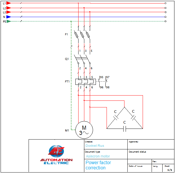
The technology has submitted requests and more companies have developed special controllers to maintain the power factor at a level closer to 1 especially in industrial environment where there are tens or hundreds of motors and this factor varies continuously depending on how many motors works a time and a such of controller is very important. The operation of these controllers is pretty simple, a number of different values of capacitors will be installed in a panel and the controller will connect or disconnect all the time necessary number of capacitors in such way as the power factor value will be maintained close to 1.
A simple drawing of how to connect these capacitors to one motor is shown at the beginning of this article.
This site is registered on wpml.org as a development site. Switch to a production site key to remove this banner.
We use cookies to ensure that we give you the best experience on our website. If you continue to use this site we will assume that you are happy with it.
Folosim cookie-uri pentru a ne asigura că vă oferim cea mai bună experiență pe site-ul nostru. Dacă continuați să utilizați acest site vom presupune că sunteți mulțumit de el.