[:en]
Energy efficiency was, is and will be one of the major topics of interest for modern society. In absolutely any industry, regardless of field of activity every company aims, through the products they sell, how they consume less power and offer higher performance as well. Power factor is one of those factors that can seriously affect the energy efficiency in different electrical systems, unless actions are taken, as we will see below.
Before to turn on technical side, I try to present an analogy, so you will understand what is actually the power factor. In our little experiment, we consider a trolley that goes like a train on railway and can be towed by a person (Fig. 1). As we know, regardless of the person’s position the trolley will not change direction, of course, we exclude idea that trolley jump off the railway.

fig. 1
If the person that tow the trolley is not exactly in the middle of the rails, always between personal position and travel direction of the trolley will be an angle, which in fig. 1 I noted as  . Now we propose some possible situations where you can find the person, while towing the trolley.
Situation 1. In this situation we consider that the angle between the position of the person who tows the trolley and its direction of travel is very large, tends to 90 degrees (Fig. 2) .When the person begin to tow the trolley will not be at all surprised that he has 

fig.2
made a serious effort, that will consume enough from his energy and the trolley will move very little, even more, when the angle is exactly 90 degrees will make all the energy that holds and the trolley will not move at all. If we had installed a energy meter this will record all the energy consumed, even though the trolley movement is almost 0.
Situation 2. Being in the situation 1, the person will not accept to tow the trolley in such conditions, completely unfavorable to him and step by step he will move slightly toward the center of the rails where the angle between its position and trolley direction tends to be zero degrees (Fig. 3). As moving closer to the center of the rail it will realize that the

fig. 3
effort is reflected in the trolley movement and moreover when the angle becomes zero realizes that all the energy consumed for tow the trolley is reflected in moving it and of course it will try to maintain this position around zero. This time our energy meter record the same energy consumed but the trolley moved as was expected.
Similar situations happens on electrical systems that contain nonlinear circuit components (coils, capacitors, diodes, transistors, etc.) which are divided into passive components (coils, capacitors) and active components (diodes, transistors, etc). We are going to disscus exclusively about passive components, because they are widely used in different electrical circuits (ex.electrical motors) and are big energy consumer.
In circuits where voltage and current are alternative depending on the nature of load, power can be defined as follows:
 – putere aparenta [VA]
 – putere activa [W]
 – putere reactiva [VAR]
these are the power ecuations for single phase supply, in case of three phase supply we have:
 – putere aparenta [VA]
 – putere activa [W]
 – putere reactiva[VAR]
If we calculare the ratio between active power and apparent power we obtain power factor:
 Now if you take a look at the situation with the trolley we see very clearly that when the angle was close to 90 degrees we consumed an amount of energy, but the movement was very low, or even zero when =
 , this produces a power factor cos very small or even zero if the angle reaches 90 degrees, after that in the situation 2 the angle decreased and tended to
  degrees, energy consumption was reflected in the movement of trolley =
 , produces a power factor cos = 1, in short I spent the same energy as in the previous case but trolley moved a lot more. So in conclusion, in order to be as much as efficient in terms of energy consumption we must find solutions so as to keep this angle as close degrees, that means a power factor cos that is closer to 1. This power factor is strongly influenced by the presence of reactive circuit elements capacitors and coils, which are the main “culprits” that the value is different from 1. Coil is leader this top since is present in electric motors construction, so in most cases we must correct an inductive power factor. If we look purely to the mathematical relationships of the three powers, we see that there is the following equality, which is also known as the power triangle:
The two circuit components (coil and capacitor) behave differently but both introduce a phase shift of 90 degrees between voltage and current, the voltage across the capacitor is behind the current 90 degrees and the electrical current through the coil being behind the voltage with 90 degrees, which is very useful in our case if we want to correct an inductive power factor we will introduce a capacitor and similarly for a capacitive power factor we will introduce a coil(fig. 4).

fig. 4
In fact to apply a power factor correction means to “force” the two alternative quantities voltage and current to oscillate in phase, the phase shift between them to be zero or very close to zero.
Calculation exemple
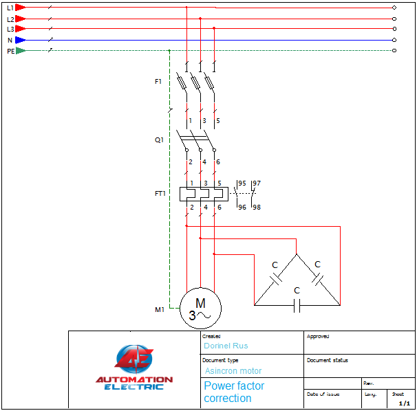
As I already mentioned in most cases we must correct an inductive power factor that is created by coils, the most common example is the electric motors. Usually on the rating plate given by manufacturer this power factor is marked with values between (0.6-0.9), together with other data related to motor. So let’s take for example an asynchronous electric motor with 30 kW active power supplied at a voltage of 400 volts at 50 Hz frequency and power factor cos = 0.8. As I already stated above, being an inductive power factor correction will have to introduce in circuit a capacitor to bring the value of cos closer to 1. For this we need to find reactive power and of course what is the value of capacitor to be introduced in the motor circuit. The reactive power can be deduced from the power triangle relation:
 So far in this relation we do not know the value of apparent power but we can deduce it very simple from active power:

Thus the apparent power is:

Finally reactive power is:
In conclusion it will be necessary to introduce in the motor circuit, in paralel with it a capacitor, that produce the equivalent of 22.5 [kvar] capacitive reactive power. How to find the capacitor value? Well quite simply, if we turn to the reactive power equation and rewrite it in another form we have the following equivalence formula:
As seen in the above equation we introduced a new term  [
[ ] called electrical reactance – which can be, inductive reactance for coils and capacitive reactance for capacitors. The equations of the two reactance are as follows:
inductive reactance: 
capacitive reactance:
where:
 – angular velocity [rad/s]
L- coil inductance [henry]
C- capacitor capacity [F]
f- frequency [Hz]
In our case we are interested in capacitive reactance in order to introduce it into the reactive power equation, to deduct the value of capacitor:
From:
we get the value of capacitor:
Value for sin will be equal to 1 because as I mentioned above regardless of circuit element introduced coil or capacitor it will introduce a phase shift between voltage and current of 90 degrees. Finally after simple calculations was obtained:
We must select a value as close as to the calculated value, if exist, or more capacitors must be mounted in parallel until you get a closer value.
The technology has submitted requests and more companies have developed special controllers to maintain the power factor at a level closer to 1 especially in industrial environment where there are tens or hundreds of motors and this factor varies continuously depending on how many motors works a time and a such of controller is very important. The operation of these controllers is pretty simple, a number of different values of capacitors will be installed in a panel and the controller will connect or disconnect all the time necessary number of capacitors in such way as the power factor value will be maintained close to 1.
A simple drawing of how to connect these capacitors to one motor is shown at the beginning of this article.
[:ro]Eficienta energetica a fost, este si v-a fi unul dintre subiectele de mare interes al societatii moderne. In absolut orice industrie, indiferent de domeniul de activitate fiecare companie isi propune, prin intermediul produselor pe care le comercializeaza, ca acestea sa consume cat mai putina energie electrica si sa ofere performanta cat mai ridicata. Factorul de putere poate afecta serios acesta eficienta energetica, in diferite sisteme electrice, daca nu se iau masuri corespunzatoare, dupa cum o sa vedem in continuare.
Inainte sa o dam pe partea tehnica, am sa incerc sa prezint o analogie, astfel incat sa intelegem ce este de fapt acest factor de putere. In micul nostru experiment, o sa consideram un carucior, care merge pe sine asemenea unui tren si poate fi tractat de o persoana (fig.1). Dupa cum bine stim, indiferent de pozitia persoanei fata de sine, caruciorul nu o sa isi schimbe directia, bineinteles excludem idea ca sare de pe sine.
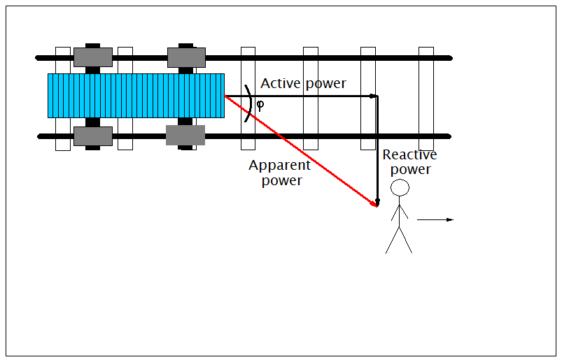
fig. 1
In cazul in care persoana care tracteaza nu se afla exact pe mijlocul sinelor, tot timpul intre pozitia personei si directia de deplasare a caruciorului o sa existe un unghi, pe care in fig. 1 l-am notat cu . Acum o sa propunem niste situatii posibile in care se poate afla persoana respectiva, in timp ce tracteaza caruciorul.
Situatia 1. In aceasta situatie consideram ca unghiul dintre pozitia persoanei care tracteaza caruciorul si directia de deplasare a acestuia este foare mare, tinde undeva spre 90 de grade (fig. 2). Cand persoana o sa inceapa sa tracteze caruciorul nu
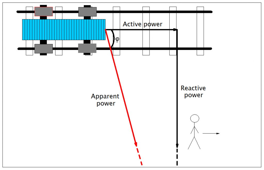
fig.2
o sa fie deloc surprinsa ca o sa depuna un efort serios, adica o sa consume destul de multa energie si caruciorul o sa se deplaseze foarte putin, ba mai mult in cazul in care unghiul este de exact 90 de grade o sa depuna toata energia care o detine si caruciorul nu o sa se deplaseze deloc. Daca am avea instalat un contor de energie, acesta o sa inregistreze frumusel si binisor toata energia consumata, chiar daca carucirul o sa cam stea pe loc.
Situatia 2. Aflandu-se in situatia 1. cu siguranta interlocutorului nostru nu o sa ii prea convina ideea sa tracteze caruciorul in asemenea conditii, complet defavorabile pentru el si o sa se deplaseze usor usor spre centrul sinelor unde unghiul dintre pozitia lui si directia de deplasare a caruciorului o sa tinda spre zero grade (fig. 3). Cu cat se deplaseaza mai
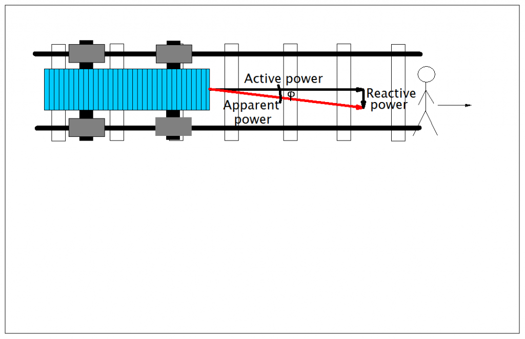
fig. 3
aproape de centrul sinelor cu atat o sa isi dea seama ca efortul depus se reflecta si in deplasarea caruciorului, ba mai mult cand unghiul devine zero isi da seama ca toata energia depusa in tractarea caruciorului se reflecta si in deplasarea acestuia si bineinteles o sa incerce sa mentina aceasta pozitie in jurul valorii zero. De data aceasta contorul nostru o sa inregistreze energia consumata dar si caruciorul s-a deplasat dupa asteptari.
Situatii similare se intampla si in sistemele electrice care contin elemenete nelimiare de circuit (bobine, condensatoare, diode, tranzistoare, etc) acestea fiind impartite in elemente pasive(bobine, condensatoare) si elemente active (diode, tranzistoare, etc). Noi o sa ne ocupam exclusiv de elementele pasive, pentru ca acestea sunt prezente in diferite circuite electrice pe scara larga (ex. motoare asincrone) si sunt mari consumatoari de energie.
In circuitele electrice in care tensiunea si curentul sunt marimi alternative in functie de natura sarcinii puterea poate fi definita astfel:
– putere aparenta [VA]
– putere activa [W]
– putere reactiva [VAR]
acestea sunt valorile puterilor pentru tensiune monofazata, in cazul tensiunii trifazate avem:
– putere aparenta [VA]
– putere activa [W]
– putere reactiva[VAR]
Daca facem un calcul simplu si raportam putera aparenta la puterea activa obtinem factorul de putere:
Acum daca aruncam o privire la situatia cu caruciorul vedem foarte clar ca cu cat unghiul
a fost mai aproape de 90 de grade s-a consumat o anumita cantitate de energie dar deplasarea a fost foarte mica, sau chiar nula cand
=
, rezulta un factor de putere cos
foarte mic sau chiar zero daca unghiul ajunge la 90 grade, dupa care in situatia 2 cand unghiul
s-a redus si a tins spre
grade, energia consumata s-a reflectat in deplasarea caruciorului
=
, rezulta un factor de putere cos
= 1, pe scurt am consumat aceeasi energie ca si in cazul precedent dar caruciorul s-a deplasat mult mai mult. Deci in concluzie, pentru ca sa fim cat mai eficienti din punct de vedere al consumului energetic trebuie sa gasim solutii astfel incat sa mentinem acest unghi
cat mai aproape de
grade, adica un factor de putere cos
cat mai aproape de 1. Acest factor de putere este puternic influientat de prezenta elementelor reactive de circuit bobina si condensatorul, care sunt principalii vinovati ca valoarea sa este diferita de 1. Bobina conduce detasat acest top deorece este prezenta in constructia motorelor electrice, deci in marea majoritate a cazurilor vom avea de corectat un factor de putere de tip inductiv. Daca privim relatiile celor trei puteri pur matematic vedem ca exista urmatoarea egalitate care mai este cunoscuta si sub denumirea de triunghiul puterilor:
Cele doua elemente de circuit (bobina si condensatorul) au un comportament diferit dar amandoua introduc un defazaj de 90 de grade intre tensiune si curent, tensiunea la bornele condensatorului este în urma curentului cu 90 grade iar intensitatea curentului electric prin bobină fiind în urma tensiunii cu 90 grade, ceea este foarte util in cazul nostru deorece daca dorim sa corectam un factor de putere inductiv vom introduce in circuit un condensator si in mod similar pentru un factor de putere capacitiv vom introduce o bobina (fig. 4).
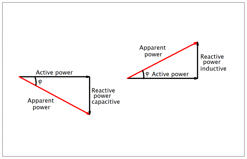
fig. 4
De fapt din punct de vedere electric a corecta factorul de putere inseamna a “forta” cele doua marimi alternative tensiune si curent sa oscileze in faza, adica defazajul dintre ele sa fie cat mai aproape de 0.
Exemplu de calcul
Dupa cum am pomenit deja in marea majoritate a cazurilor avem de corectat un factor de putere inductiv care este creat de bobine, cel mai des intalnit exemplu este cel al motoarelor electrice. De obicei pe placuta cu informatii data de producator acest factor de putere este marcat avand valori intre (0.6-0.9), impreuna cu alte date legate de motorul respectiv. Asadar sa luam ca exemplu un motor electric asincron cu o putere activa de 30 kW, alimentat la o tensiune de 400 de volti la frecventa de 50 Hz si un factor de putere cos=0.8. Dupa cum deja am afirmat mai sus fiind vorba de corectia unui factor de putere inductiv v-a trebui sa introducem in circuit un condensator pentru a aduce valoarea lui cos
cat mai apreoape de 1. Pentru acesta trebuie sa aflam care este puterea reactiva si binenteles care este valoarea condensatorului care trebuie introdus in circuitul motorului. Din formula triunghiului puterilor putem simplu deduce valoarea puterii reactive:
Decocamdata in aceasta relatie nu cunoastem valoarea puterii aparente dar o putem deduce foarte simplu din formula puterii active:
De aici scoatem puterea aparenta:
Revenind la puterea reactiva:
In concluzie v-a fi necesar sa introducem in circuit in paralel cu bobinele motorului un condensator care sa produca echivalentul a 22.5 [kVAR] putere reactiva capacitiva. Cum aflam valoarea condensatorului ? ei bine destul de simplu, daca ne intoarcem la sistemul de ecuatii aferent celor 3 tipuri de puteri si rescriem sub alta forma ecuatia puterii reactive vom avea urmatoarea formula echivalenta:
Dupa cum se vede in ecuatia de mai sus am introdus un nou termen care poarta denumirea de reactanta-acesta putand fi in fuctie de natura elementului reactiv, inductiva in cazul bobinelor si capacitiva in cazul condensatoarelor. Ecuatiile celor doua reactante sunt astfel:
reactanta inductiva:
reactanta capacitiva:
unde:
-viteza unghiulara [rad/s]
L-inductanta bobinei [henry]
C- capacitatea condensatorului [F]
f-frecventa [Hz]
In cazul nostru suntem interesati de reactanta capacitiva pe care o sa o introducem in ecuatia puterii reactive, de unde o sa deducem valoarea condensatorului:
Din:
rezulta valoarea capacitorului:
Valoarea lui sin v-a fi egala cu 1 deorece dupa cum am amintit mai sus indiferent de elementul de circuit introdus, bobina sau condensator acesta v-a introduce in circuit un defazaj intre tensiune si curent de 90 de grade. In final dupa calcule simple s-a obtinut:
Se v-a alege o valoare standard cat mai aproape de valoarea calculata, daca exista, sau se vor monta mai multe condensatoare in paralel.
Tehnologia s-a supus cerintelor si mai multe companii au dezvoltat controlere speciale pentru a mentine acest factor de putere la un nivel cat mai aproape de 1. In mediul industrial unde exista zeci sau sute de motoare si acest factor variaza continuu in functie de cate motoare functioneaza la un moment dat, un asemenea controler este foarte important. Functionarea unui asemenea controler este destul de simpla, un numar de condensatoare de diferite valori vor fi montate intr-un dulap iar controlerul va cupla sau decupla tot timpul numarul necesar de condensatoare, astfel ca valoarea factorului de putere va fi mentinuta aproape de 1.
O schema simpla de conectare a acestor condensatoare la un motor este prezentata in schema de la inceputul articolului.
[:]